Various test rigs are used to validate the diagnosis and prognosis methods developed at the Institute. With the help of these test rigs wear mechanisms are analysed and so-called run-to-failure curves are generated which enables the training of data-based diagnosis and prognosis models through machine learning algorithms.
In the past the FSR operated an asynchronous motor test rig with which different types of load such as radial forces or electric current were applied to test deep groove ball bearings to simulate different failure cases. In addition a further test rig enabled the investigation of deep groove ball bearings of a fan with a controlled air flow (constant load). Vibration sensors and sensors for measuring the phase currents of the motor were used to determine the wear condition.
At present two test rigs are ready for use at the FSR for research into prognostics and health management methods.
Test rig for the investigation of multi-copter drive trains
The FSR operates a test rig for the investigation of the drive trains (battery, electronic speed controller, brushless direct current motor, propeller) of multicopters with regard to their wear and tear as well as the available power, which was built up in the course of the MAAM project.
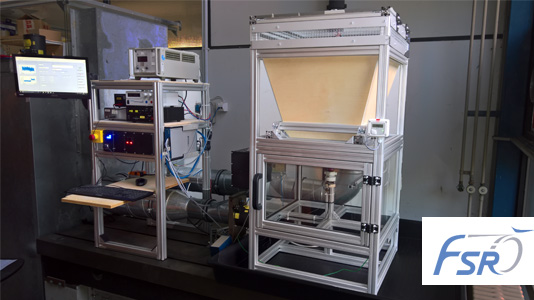
With an optional wind generator the influences of the airflow in flight can be taken into account. The test rig is equipped with sensors for measuring thrust force, air speed, rotational speed, temperature and humidity. The control and data acquisition is done via LabView using the external NI 6353 board with 32 AI, 48 DIO and 4 AO channels. Thanks to the modular design, it is possible to introduce specific error cases into the individual components of the drive train and analyse their effects.
Actuator and transmission test bench
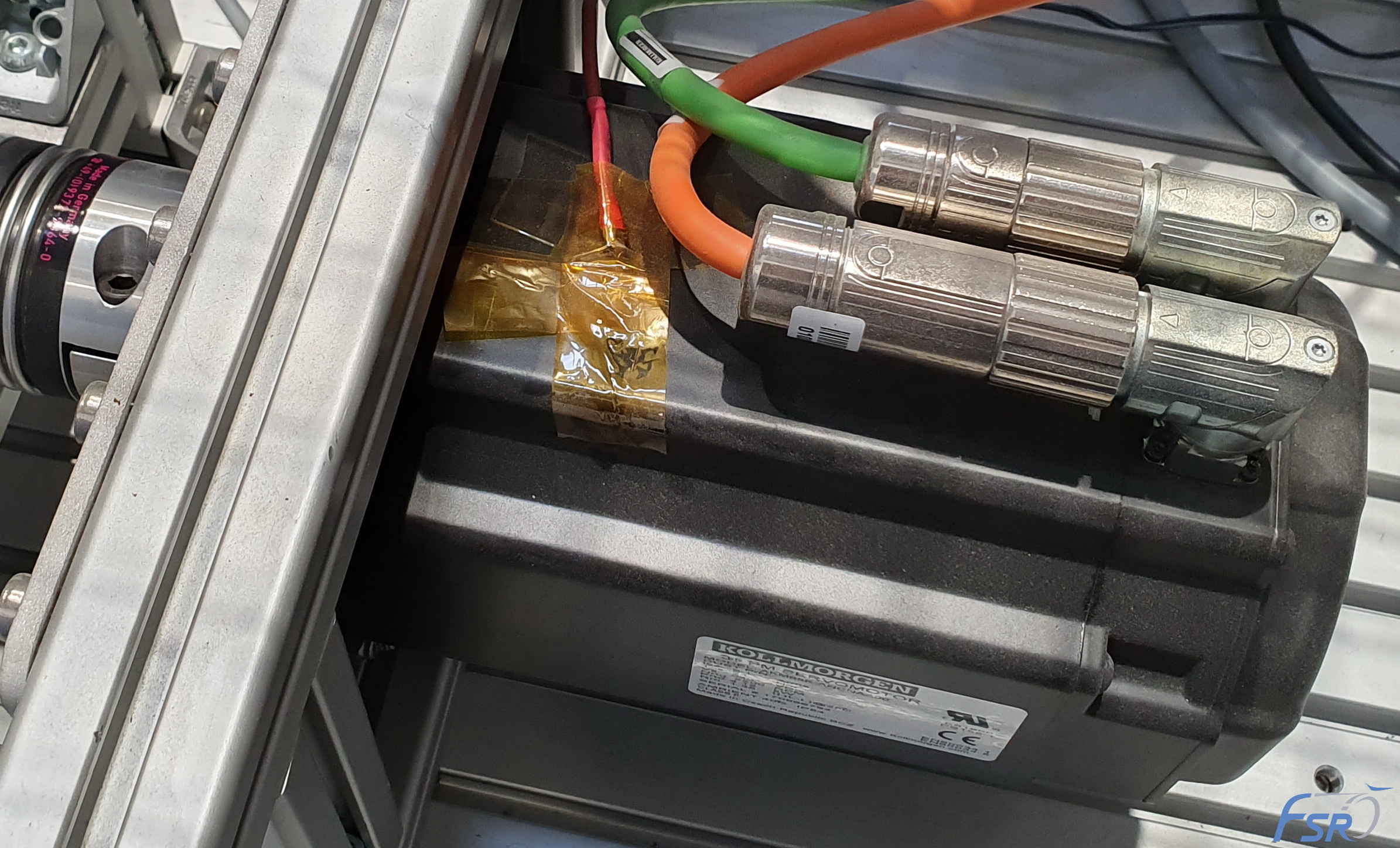
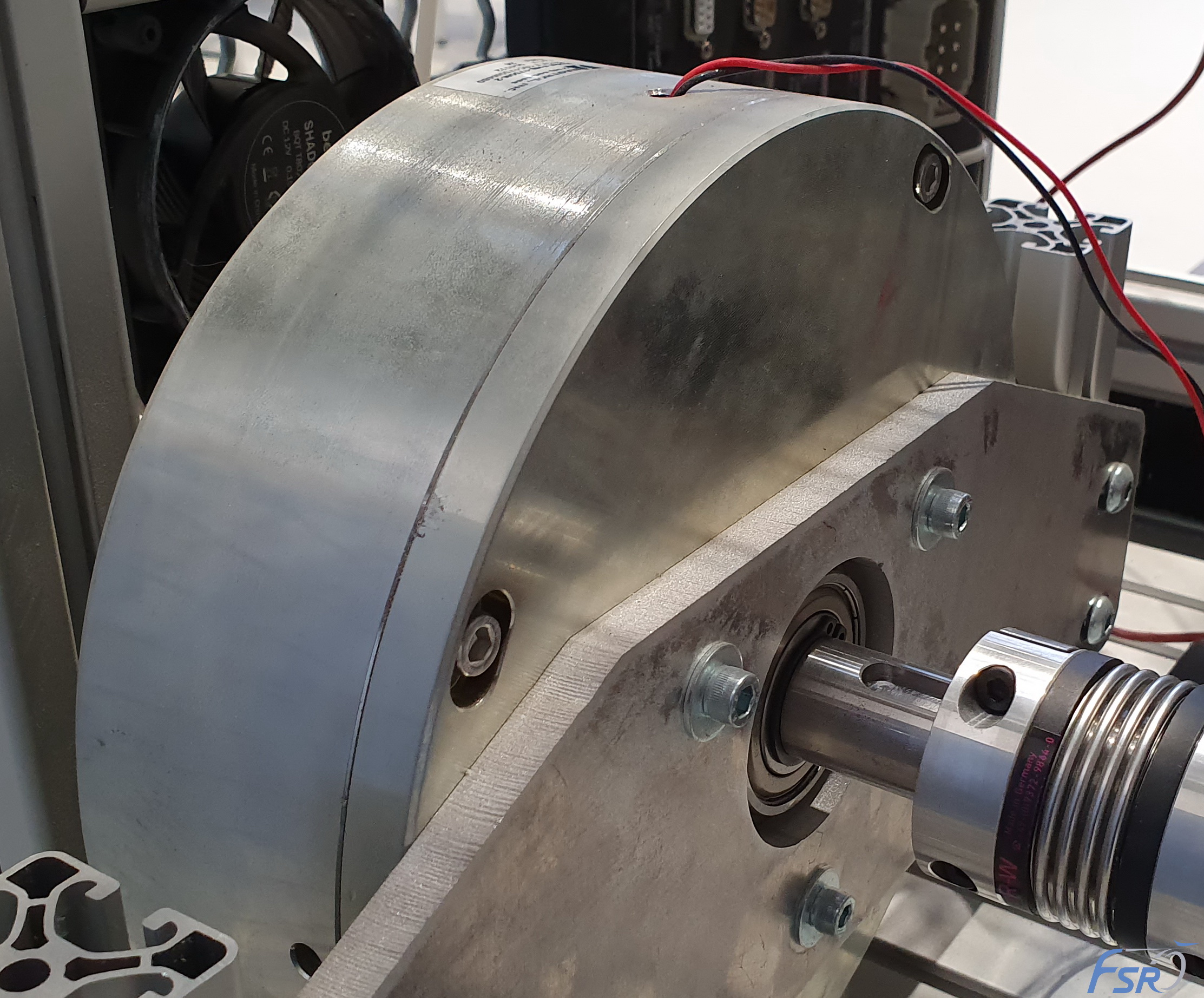
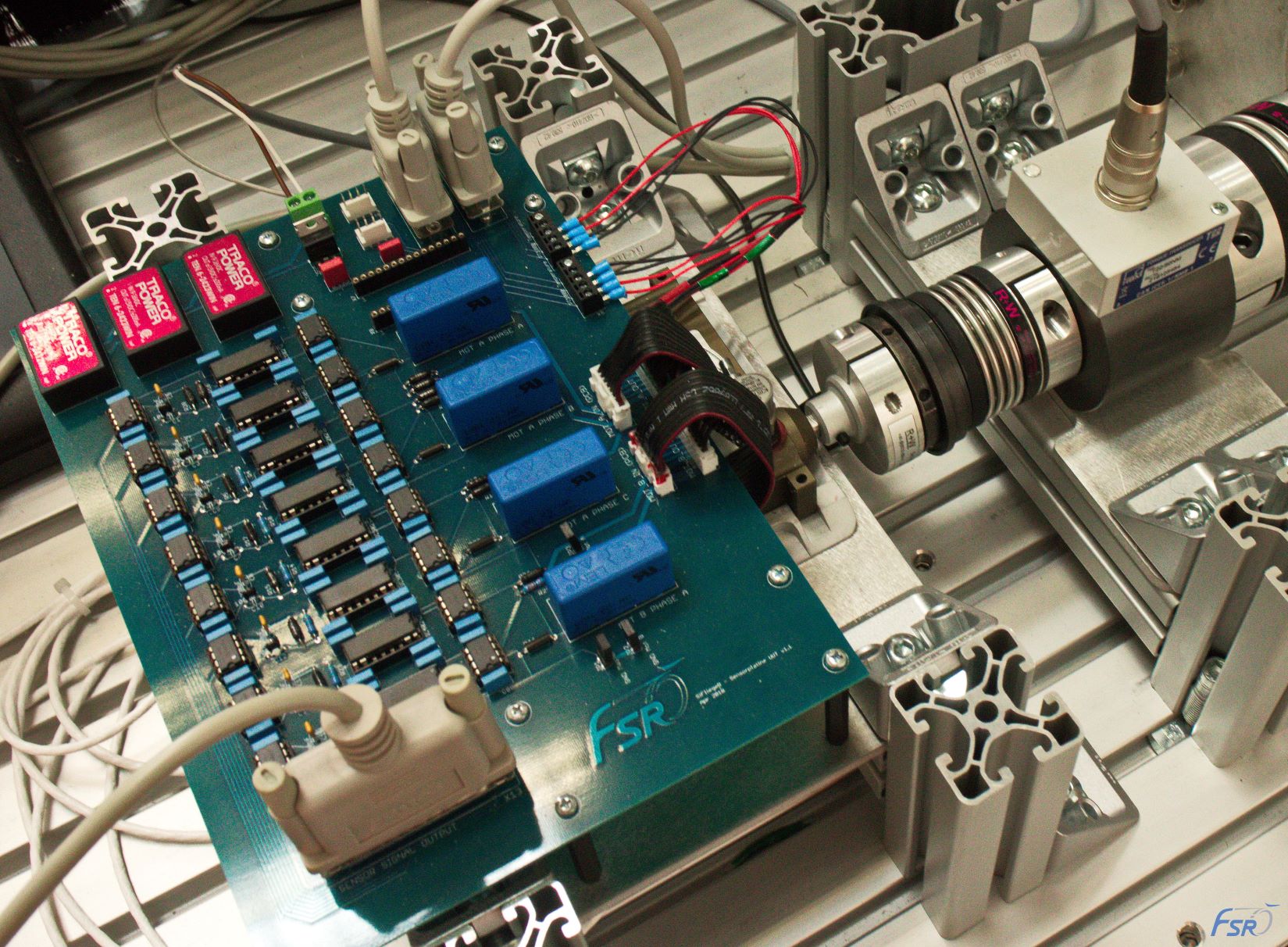
Within the SiFliegeR project an actuator test rig was built. With this test rig the use and degradation of electromechanical actuators can be investigated. The built-in torque motor allows an active force application so that dynamic loads, such as those occurring on control surfaces during flight, can be mapped. Thanks to the extensive sensor technology (torque, vibration, phase currents & voltages, temperatures, etc.), the condition of the actuator can be recorded.
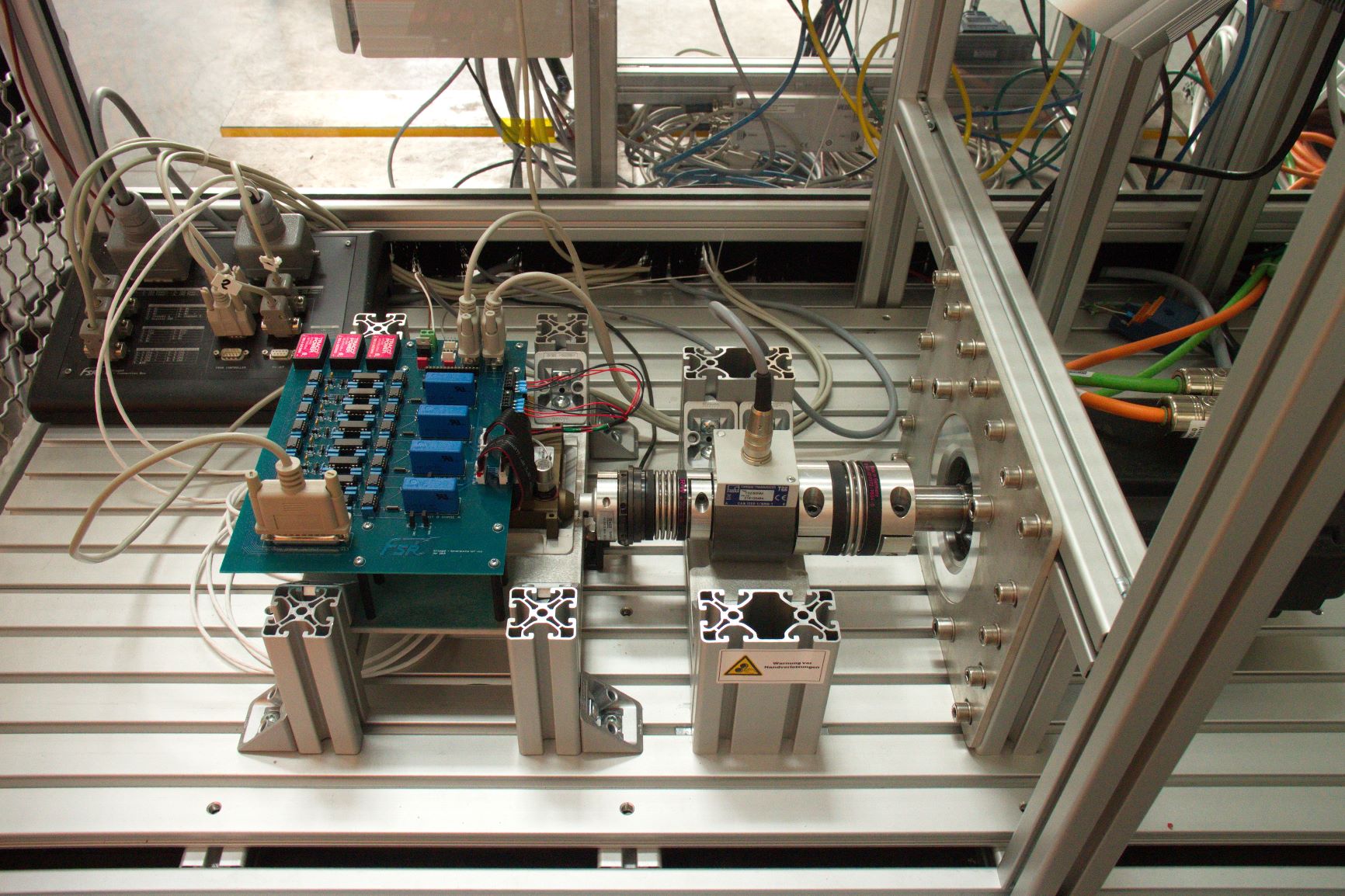
The modular design allows easy modification of the test bench. Instead of actuators, for example, gearboxes are also examined with regard to their wear under different loads. The torque motor is used as speed sensor and a hysteresis brake for load application.
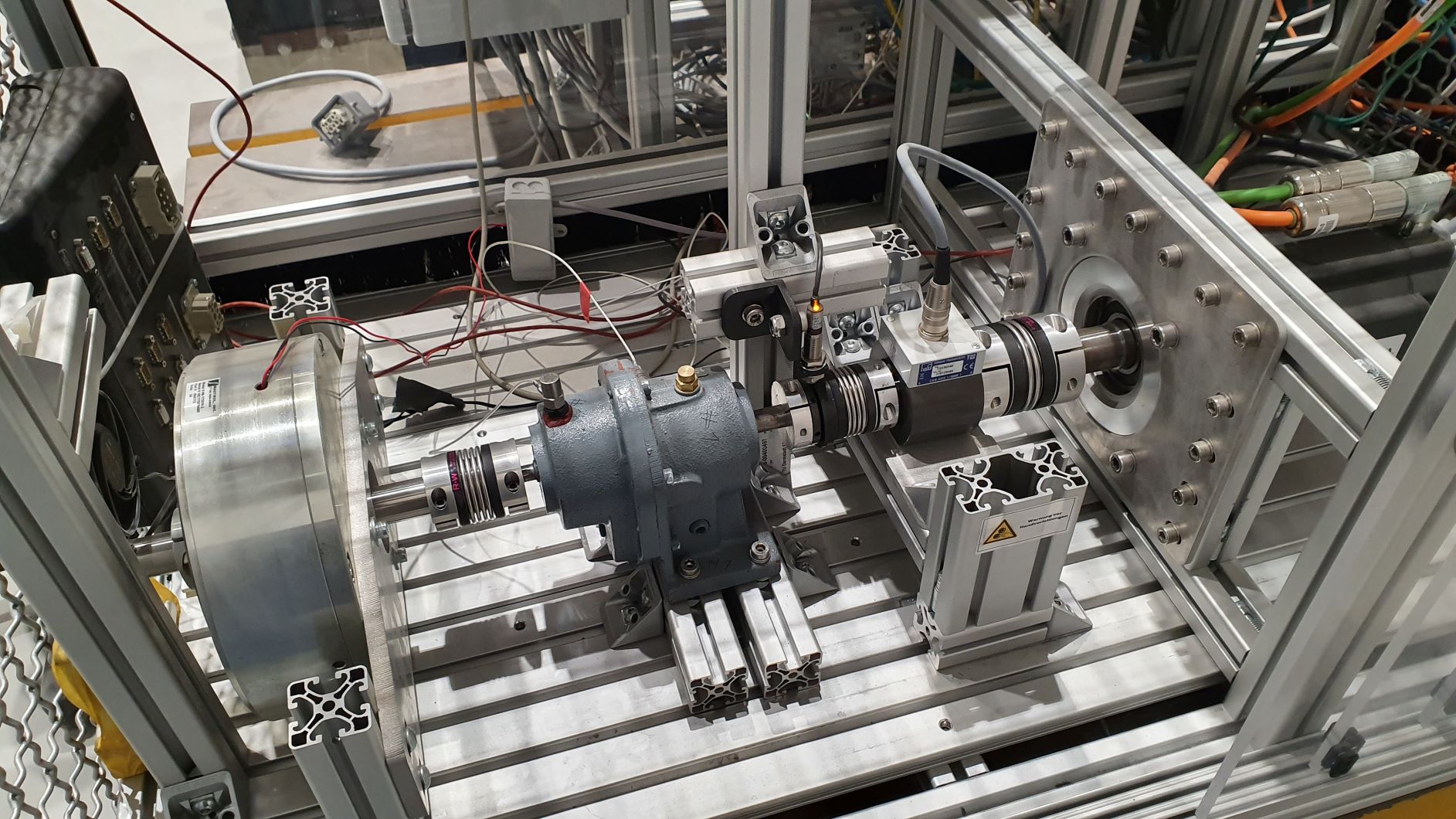
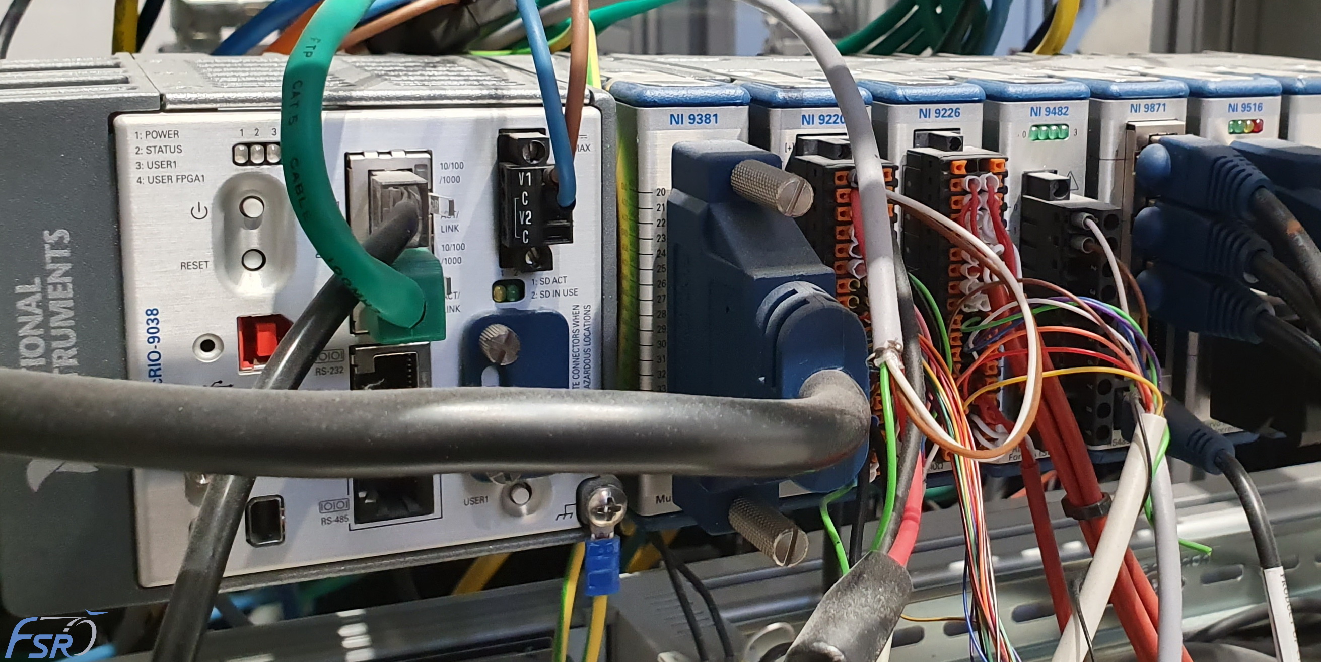
For further research projects, the flexible design also offers the possibility to quickly adapt the setup for the investigation of other rotating parts. A comprehensive measurement hardware is available which can be used flexibly via the compatRio from National Instruments in real-time and also with the support of an FPGA.